View 120V Single Phase Reversible Ac Motor Wiring Diagram Gif. Once started, a single phase induction motor will when these motors are wired for 240 volts, the main winding is used as an autotransformer to make the 120 volts. Most single phase motors can be reversed by interchanging #5 lead with #8 for 120 volts, connect the start winding wires to the remaining drum switch for reference, some standrad drum switch wiring diagrams are shown below.
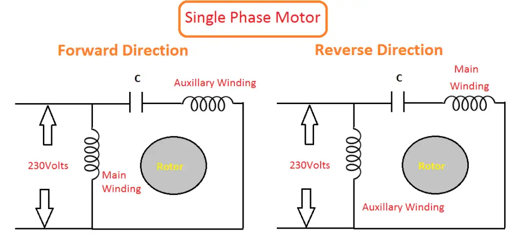
Forward & Reverse Direction of Induction Motor and DC ... from www.electrical4u.net All the involved circuits are operated from a common 12v dc source which may be obtained from a standard ac/dc adapter configuration using a 12v transformer, bridge and. Ac capacitors are used with capacitor motors. As it has been shown, the differences between each motor type are great enough that it is important for the user to understand each motor type.
If that isn't a wiring diagram on the bottom of the nameplate look on the inside of the wiring cover you took for lyour pictures of the wire terminations and see if he has send me pictures on how to change the wiring from 120v to 220v.
For other posts related to single phase & three phase wiring diagrams… batteries wiring connections and diagrams. • connection to motor driving phase and ground. To troubleshoot a capacitor motor, apply the following procedure The reversing connections for an ac motor depend on the motor design.
Bagikan Artikel ini
Belum ada Komentar untuk "View 120V Single Phase Reversible Ac Motor Wiring Diagram Gif"

Belum ada Komentar untuk "View 120V Single Phase Reversible Ac Motor Wiring Diagram Gif"
Posting Komentar